我が家のSYNP MIDI搭載memorymoogのボイスカードが1枚、ついにオートチューン補足範囲外へ出てしまう状況が発生してしまいました。時間経ってから何度かオートチューンすると直る時もあるんですけども、精神衛生上宜しくない。
MOOG ONEとも鳴らし比べしたい所ですし、そろそろ重い腰を上げてトリムをグリグリしようと思った次第。
面倒なチューニング作業ですが、今回は業者には出さず、自分で頑張ってみようかなと。覚えちゃえば一々入院させる必要も無くなるかもしれないですしね。
ちなみに、伝統のラダーフィルターに加え、CEM3340 VCOチップと50%以上で飽和するVCAの荒さが特徴的なmemorymoog、こんな音がします。
以下本題、メモ帳からコピペした備忘録になります。
【備忘録】memorymoog tuning
※下記、実際やってみた後に必要なら写真追加、日本語訳の修正をする予定です。
INTRODUCTION
Most Of the adjustroents below are Interdependent procedures which MUST be performed in the order presented, however, normal oscillator recalibration WILL NOT require all steps to be performed.
以下の調整のほとんどは、提示された順序で実行されなければならない相互依存の手順ですが、通常の発振器の再キャリブレーションでは、すべての手順を実行する必要はありません。
The Memorymoog PROMs have a considerable amount of diagnostic software built in,
therefore, try the SOFTWARE TUNING procedure FIRST and the test equipment procedure only as necessary. The replacement of an IC that has an associated trim potentiometer will require recalibration, except that the replacement of a 3340 oscillator IC may ONLY require SOFTWARE oscillator TUNING – again try the SOFTWARE TUNING FIRST!
Memorymoog PROMはかなりの量の診断ソフトウェアを内蔵していますので、
ソフトウェアチューニング手順を最初に行った後、必要に応じテスト装置手順を試してください。
関連するトリムポテンショメータを備えたICを交換するには、3340発振器ICを交換する場合にのみ再校正が必要です。
ソフトウェアチューニングをもう一度試してみてください!
THE SOFTWARE OSCILLATOR TUNING OUTLINE
ソフトウェアオシレータのチューニングの概要
◆ Find the out-of-tune oscillator (s ) .
オートチューン範囲外のオシレーターを探します。
◆ Note the AUTOTUNE parameters and perform minor recalibration where necessary.
AUTOTUNEのパラメータと必要に応じて軽度の再校正を行います
● Perform major oscillator recalibration.
主要なオシレータの再校正を実行します。
LOCATING THE OUT-OF-TUNE V01CE{S) AND oscillator: s
チューニング外のボイスとオシレータがとれかを調べます。
● Hit 2, ENTER for the straight brass program #2.
2を入力した後にENTERを押し、ナンバー2のBrass音色にします。
● Hit KB mode, 1 and ENTER to put the Memorymoog into the “POLY 1” mode (cyclic mode). The display will read “EDIT”.
KBモード、1、ENTERキーを押して、Memorymoogを “POLY 1″モード(cyclic mode)へ。ディスプレイに “EDIT”が表示されます。
● Hit C, 5 and ENTER to electrically center the oscillator frequency settings of oscillators 2 and 3 (unison). The display will read “FREQ CTR”.
C、5、ENTERキーを押して、オシレータ2と3の発振器周波数設定を電気的に中央に合わせます(ユニゾン状態にする)。 ディスプレイに “FREQ CTR”が表示されます。
● Hit C, 4 and ENTER and listen for an out-of-tune voice (rapid beating sound) by repeatedly playing the high C key. The display will initially read “DEFEAT ?” and then will indicate the voice being played, “1”, “2”, etc. WRITE DOWN THE OUT-OF-TUNE VOICE NUMBER!
Cキー、4キー、ENTERキーを押し、鍵盤の高いCキーを繰り返して弾くことで、音が出ない、またはドリフトしたボイスを確認します。ディスプレイには最初「DEFEAT?」と表示されますが、鍵盤を弾くことで “1”、 “2”などの再生されたボイスカード番号を示します。チューンアウトしたボイスカード番号を書き留めてください!
For any out-of-tune voice, isolate and listen to each OSCILLATOR by turning on and off the individual waveform switches (SAWTOOTH) for oscillators 1, 2 , 3. This will locate the out-of-tune oscillator – WRITE DOWN THE OSCILLATOR NUMBER!
アウトオブチューニングのボイスについては、オシレーター1、2、3の個々の波形スイッチ(SAWTOOTH)をオンまたはオフにして、各オシレーターを分離して聴いて確認してください。
NOTING THE AUTOTUNE PARAMETERS
オートチューンのパラメータを知る
● Hit C, 7, ENTER and ENTER again; the display will then query ‘VOICE ?”;
hit the number of the voice above, which was out-of-tune, BUT DO NOT HIT ENTER!!
Wait a second and the display will then query “OSC ?”; hit the number of the oscillator above which was out-of-tune but again, DO NOT HIT ENTER; the display will then flash an expanded scale version of the AUTOTUNE voltages in a hexidecimal (HEX) format indicating from left to right a two digit RANGE, SCALE and HIGH TRIM code.
C、7、ENTER、ENTERをもう一度押します。ディスプレイは「VOICE?」と聞いてきます。
音程が外れている上記のボイス番号をタイプしますが、 まだENTERしてはいけません!!
しばらく待つとディスプレイは「OSC?」と聞いてきます。 上記のオシレーターの番号を打ってください。それより上の音は出ませんでしたが、もう一度ENTERを押してください。
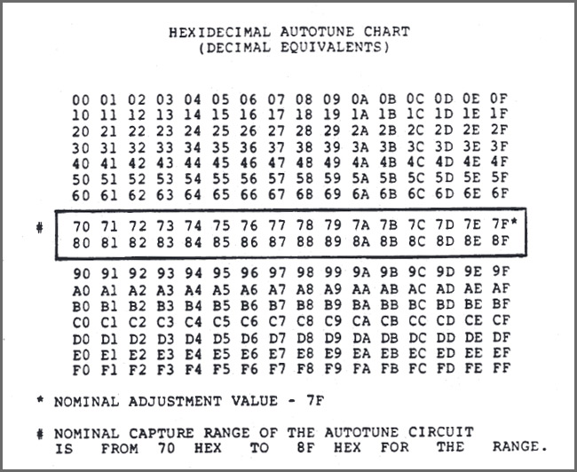
ディスプレイはAUTOTUNE電圧の拡張スケールバージョンを16進数(HEX)形式で点滅させ、左から右に2桁のRANGE、 SCALEとHIGH TRIMコードを表示します。
● WRITE THESE VALUES DOWN with associated voice and oscillator numbers from above. Note that the second digit may “bobble” +/- one digit. An “ideally” tuned oscillator would display 7F 7F 7F. See the accompanying hexidecimal chart.
これらの値を上から関連する音声とオシレーターの番号で書き留めます。 2桁目は+/- 1桁で「揺らぐ」ことがあります。 「理想的に」同調された発振器は、7F 7F 7Fを表示します。付随する16進数チャートを参照してください。
“DEAD OSC 表示とは”
The AUTOTUNE voltages will flash so long as the oscillator is tuned within a +/- 50c range. Howevex, if the oscillator’s tuning is outside this capture range, the display will indicate “DEAD OSC”. The oscillator usually is not dead but simply outside the AUTOTUNE range. See the MAJOR OSCILLATOR RECALIBRATION section of this procedure.
オシレータが+/- 50cの範囲内でチューニングされている限り、AUTOTUNE電圧は点滅します。オシレーターのチューニングがこのキャプチャ範囲外の場合、ディスプレイには “DEAD OSC”と表示されます。”DEAD OSC”と言っても発振器は通常死んではいません。単にAUTOTUNEの範囲外を示しています。この手順の主要なオシレータのリカバリの項を参照してください。
INOR RANGE ADJUSTMENT.
マイナーレンジ調整。
If the SCALE and HI are within +/- 2 digits of the RANGE, but the RANGE is too far from the 7F nominal value, ” a simple range adjustment is all that is necessary. * indicates the trim being adjusted in the example.
SCALEとHIがRANGEの+/- 2桁以内で、RANGEが7Fの公称値から離れすぎている場合は、 “単純なレンジ調整が必要です。*はこの例で調整されているトリムを示します。
EXAMPLE: VOICE 1 OSC 1
RANGE:52* SCALE:54 HI:53
A difference of 1 or 2 between these values means the oscillator is close enough in SCALE and HIGH TRIM but it’s RANGE is too low.
これらの値の差が1または2の場合、オシレータはSCALEとHIGH TRIMで十分に近いですが、RANGEが低すぎます。
EXAMPLE: VOICE 1 OSC 1
RANGE:7F* SCALE:81 HI:80
Readjustment of the RANGE to the 7F nominal value also brings the SCALE and HIGH TRIM to acceptable values.
RANGEを7Fの公称値に再調整すると、SCALEとHIGH TRIMも許容値になります。
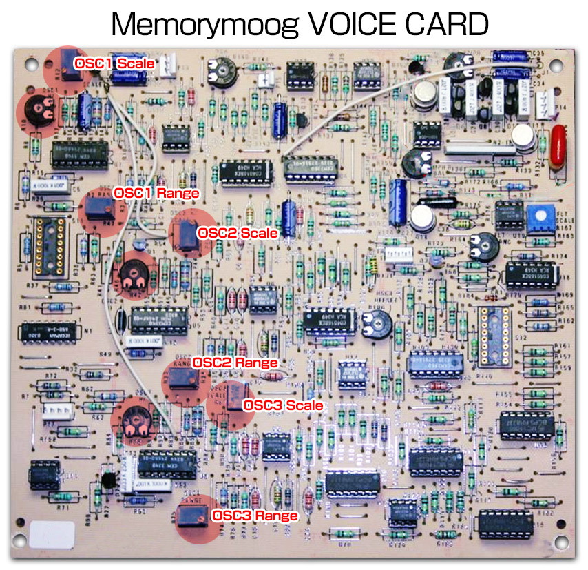
note: to INCREASE the RANGE readings, turn OSC 1 i 2 RANGE trims COUNTER-CLOCKWISE and OSC 3 RANGE trim CLOCKWISE.
注:レンジの読み取り値を増やすには、OSC 1 i 2 RANGEを回してCOUNTER-CLOCKWISEとOSC 3 RANGEをCLOCKWISEに調整します。
● TOUCH-UP TUNING.
タッチアップチューニング。
Complete readjustment will be necessary if there are differences between the three oscillator values exceeding +/- 2 DIGITS.
Below is an example of this condition.
*indicates the trim being adjusted in the example.
+/- 2 DIGITSを超える3つのオシレータ値に違いがある場合は、完全な再調整が必要です。
以下はこの状態の例です。
*は例で調節されているトリムを示します。
EXAMPLE : VOICE 1 OSC 1
RANGE:A3 SCALE:9E* HI:94
These oscillator values are very apart; first adjust the SCALE
approximately EQUAL the RANGE. (Note that the SCALE trim affects the RANGE and HI)
SCALE trim note: To INCREASE the SCALE readings, turn OSC 1 4 3 SCALE trims CLOCKWISE and OSC 2 SALE COUNTER-CLOCKWISE.
これらのオシレータ値は非常に離れています。最初にスケールを調整する
RANGEとほぼ同じです。 (SCALEトリムはRANGEとHIに影響します)
SCALEトリムノート:
SCALEの読みを増やすには、OSC 1 4 3を回してCLOCKWISEとOSC 2 SALE COUNTER-CLOCKWISEを調整します。
EXAMPLE: VOICE 1 OSC 1
RANGE:CI SCALE:C3 HI:BO*
Next adjust the TRIM to approximately EQUAL the RANGE and SCALE. HI trim note:
To INCREASE the “HI” readings, turn, OSC 2 & 3 HI trims CLOCKWISE and OSC 1 HI trim COUNTER-CLOCKWISE.
次に、TRIMをRANGEとSCALEとほぼ等しくなるように調整します。
ハイトリムノート:
「HI」測定値を増やすには、OSC 2&3 HIがCLOCKWISEとOSC 1 HIトリムカウンタークロックを調整します。
EXAMPLE: VOICE 1 OSC 1
RANGE:CI* SCALE:C3 HI:CI
Lastly adjust the RANGE to the nominal value of 7F and the other adjustments will follow automatically.
EXAMPLE: VOICE 1 OSC 1
RANGE:7F SCALE:81 HI:7F
This is the end of the software adjustment procedure for minor VOICE/OSCILLATOR recalibration. If it is necessary to proceed to identify other out-of-tune voices and/or oscillators, depress and “hold” the ENTER switch until the display
reads “ENTER”; then hit ENTER again and the display will inquire as above for which VOICE and oscillator to display. An ENTER instruction will not be accepted if the flashing display is in an unlite state. To exit this mode of operation, hit ENTER when the display queries “VOICE?”.
● MAJOR OSCILLATOR RECALIBRATION.
Oscillators for which the display indicates “DEAD OSC” can be brought into range “by ear” using a tuned oscillator of the same VOICE as a reference source assuming the oscillator is simply out of the AUTOTUNE capture range.
This procedure will be required for a 3340 VCO replacement or for troubleshooting a suspected VCO that is swapped on a VOICE CARD to confirm tuning instability.
● Defeat all voices EXCEPT the one to be recalibrated. If, for example, VOICE 1 is out-of-tune, the following routine will defeat the other VOICES (2 through 6):
C, 4, ENTER “DEFEAT ?”, 2 ENTER
C, 4, ENTER “DEFEAT ?”, 3 ENTER
C, 4, ENTER “DEFEAT ?”, 4 ENTER
C, 4, ENTER “DEFEAT ?”, 5 ENTER
C, 4, ENTER “DEFEAT ?”, 6 ENTER
This allows repeated notes to be played in the cyclic mode (POLY MODE 1) with only the out-of-tune oscillator showing in the ALPHANUMERIC DISPLAY.
● Hit 2, ENTER for the straight brass PROGRAM 12.
● Hit 4 foot OCTAVE for oscillators 1, 2 & 3.
● Hit C, 6, ENTER to clear out previous
AUTOTUNE voltages.
● Hit C, 5, ENTER for a unison sound.
● Hit C, 4, ENTER and repeatedly play the high C key. Note that the ALPHANUMERIC display should ONLY show the VOICE to be recalibrated. If not, go back to the defeat routine above.
● Using the waveform selection switches (in this case, the SAWTOOTH switches),
compare the out-of-tune oscillator with ONE of the good oscillators – the second good oscillator should be turned off.
● Hold down the low A (Al) and adjust the associated RANGE trim for unison.
● Hold down the MIDDLE (third) A (A3) and initially adjust the associated SCALE trim for “unison” but note the number of turns needed for unison (example: three turns clockwise). The SCALE trim significantly interacts with the RANGE trim, therefore, “overshoot” this SCALE trim by twice the number of turns (example: additional turns clockwise).
Repeat the six RANGE and SCALE adjustments until both the low, and middle A notes will zero beat.
● Hold the High A (A5) and adjust the associated HI trim for zero beats.
Refer to the TOUCH UP tuning procedure above for further minor adjustments if the
oscillator will not autotune. When this tuning procedure is completed, hit C4 , ENTER, ENTER to ENABLE all six voices. The display will then indicate “ENABLE”.
ABBREVIATED OSCILLATOR TUNING WITH EQUIPMENT
Using test equipment, a shortened oscillator tuning procedure may be accomplished as follows:
Perform POWER SUPPLY, DMUX and PRELIMINARY OSCILLATOR TUNING (Steps I, II and III); omit the next four steps – preliminary CONTOUR/GLIDE, preliminary COMMON ANALOG, FILTER tuning and VCA balance (Steps IV, V, VI and VII) -unless an associated part has been replaced; proceed with MAIN OSCILLATOR TUNING (Step VIII), SCALING adjustments (Step IX) OCTAVE TRANSPOSE (Step X).
abbreviated oscillator tuning only Steps I, II, III, VIII, IX and X.
The remaining adjustments, such as MODULATION OSCILLATOR (Step XI), PITCH WHEEL Offset (Step XII), VOICE MODULATION Offset (Step XIII) and FOOT PEDAL adjustments (Step XIV) can all be skipped unless associated parts have been replaced.
NOTE:
NOTE: When performing MAIN OSCILLATOR tuning Step VIII be aware that the SCALE trim SIGNIFICANTLY offsets the RANGE trim. To expedite tuning time, “over-shooting” the SCALE trim by factor of two in the opposite direction speeds tuning, eg. if the SCALE is 10c flat, turn the SCALE adjustment approximately 20c sharp.
WARMUP AND ACCURACY
Turn power on and allow unit to warm up at least ten minutes before attempting calibration. Use of a 4-1/2 digit DVM is NECESSARY for accurate calibration.
I. POWER SUPPLY ADJUSTMENTS
-15V SUPPLY ADJUSTMENT (4-1/2 DIGIT DVM REQUIRED)
1. Attach the negative DVM probe to the negative side of C74 and the positive probe to the negative side of C75, both on the DMUX board.
(Page 44) 一旦ここまで。